Here we go.
All pieces removed from the chassis. No turning back now :)
The actual interior height is 67 mm. Also, the bottom plate is raised by 8 mm (to seat CD transport assembly on the plate). Even with 10 mm spacer to mount motherboard (which I/O rear panel is 44.45 mm tall) and FlexATX PSU (40.3 mm), the chassis is plenty tall enough for them.
Also, the depth of the chassis is deep enough so that the Mini-ITX motherboard (170 mm) and slim optical drive (126 mm), expecting less than 1 cm overlap. <sigh of relief/>
The front-panel PCB needs to be studied closely.
It hosts the VFD, IR Detector (remote control receiver), and 8 buttons. The dimension of the PCB will be measured precisely to produce the custom PCB for the PC front panel interface. The front panel buttons make contact with the tactile switches (5 mm tall, <<1 mm travel) on the PCB so when buttons are depressed the switches make contacts.
References:
ATX Specification v2.2 - formfactor.org
Form Factor of 5 1/4" 9.5mm and 12.7mm Height Optical Drives - SFF Committee
Modding Onkyo CD Player to XBMC MPD or XMMS2 Linux Jukebox, etc.
オンキョーINTEC CDプレーヤーをXBMCMPD/XMMS2ジュークボックスに換装するプロジェクト,等々。
Tuesday, April 12, 2011
Sunday, April 10, 2011
PicoScope 2104: diyer's perfect solution
Here's my first impression on PicoScope, a USB Windows based oscilloscope by PicoTechnology (U.K.). I ordered the hand-held entry-level model (2104) from Newark.com. This scope is a compact (essentially a bulky probe with USB leads) and economical (~$200) solution, perfect for DIYers.
This is it. The body of the probe houses all the essential data-acquisition electronics, and any post-processing and the waveform display are performed on PC. The scope only requires a USB 2.0 connection as it is USB-bus powered.
The spec:
Packaging: The scope came in a plain box,
which contains a scope storage bag and an intro-to-picoscope poster:
The scope is obviously in the bag along with Quick Start Guide, Software and Reference CD-ROM, and a bag of accessories.
The contents of the accessory bag:
The PicoScope Software installed smoothly on my PC and has been running hiccup free so far (Windows 7, Intel Core2Duo 3GHz, 4 GB memory). Here's a screen shot:
I find that the user interface is pretty straight forward and self-explanatory (that is, if you've used scopes in the past) based on my brief experience.
The body of the scope has 1 lighted button, which brings the start/stop control to the user's fingertip. Also, the button illuminates green (running) or red (not running) to indicate the scope's status:
As seen in the picture above, the probe tip is also lit, which helps tremendously to locate test points, IC legs, etc.
This is it. The body of the probe houses all the essential data-acquisition electronics, and any post-processing and the waveform display are performed on PC. The scope only requires a USB 2.0 connection as it is USB-bus powered.
The spec:
- Vertical Resolution: 8bits
- Analog Bandwidth: 10 MHz
- Maximum Sampling Rate: 50 MS/s real-time
- Time Base: 10 ns/div to 50 s/div
- Buffer Size: 8k samples
- Probe: 1M Ohm, 20 pF, AC/DC coupling
- Voltage Ranges: ±100 mV to ±20 V in 1, 2, 5 V steps
- Accuracy: 3% (voltage) and 100 ppm (time)
- Connected and powered by USB
- 5 year warranty
Packaging: The scope came in a plain box,
which contains a scope storage bag and an intro-to-picoscope poster:
The scope is obviously in the bag along with Quick Start Guide, Software and Reference CD-ROM, and a bag of accessories.
The contents of the accessory bag:
The PicoScope Software installed smoothly on my PC and has been running hiccup free so far (Windows 7, Intel Core2Duo 3GHz, 4 GB memory). Here's a screen shot:
I find that the user interface is pretty straight forward and self-explanatory (that is, if you've used scopes in the past) based on my brief experience.
The body of the scope has 1 lighted button, which brings the start/stop control to the user's fingertip. Also, the button illuminates green (running) or red (not running) to indicate the scope's status:
As seen in the picture above, the probe tip is also lit, which helps tremendously to locate test points, IC legs, etc.
Wednesday, March 16, 2011
VFD & USB-to-UART Module
ここ(昔お世話になった方のブログ)でこんなものを発見。
My old over-the-internet Japanese acquaintance (whom I was grateful to hear his safety after the earthquake) posted a blog entry on using this USB-to-UART module (essentially an FTDI FT232R evaluation module):

In the U.S., we can get this little PCB piece from Mouser for $17.50 a piece. This looks a lot more appealing than other offerings such as this or this.
このモジュールの用途は前面パネルのVFD(蛍光表示管)を元の(Fig.A)からNoritakeの(Fig.B)に変える予定。このVFDモジュール(GU280X16G)CMOS 又は RS-232のインターフェースオプションがあるがCMOSの方を購入予定。(USBでPCに直接繋ぐか、インターフェースコントロール用のMCUを介して繋ぐかのオプションが出来るから。)
This module can be used to interface a Noritake VFD (Fig. B, which is to replace the original shown in Fig. A) with PC. There are 2 interface options for this VFD (GU280X16G): CMOS or RS-232. My plan is to go with the CMOS route so it can be connected to the PC directly (via USB module above) or indirectly via a microcontroller which checks the front-panel inputs (buttons & IR remote) even when the PC is off (more on this later).
My old over-the-internet Japanese acquaintance (whom I was grateful to hear his safety after the earthquake) posted a blog entry on using this USB-to-UART module (essentially an FTDI FT232R evaluation module):

In the U.S., we can get this little PCB piece from Mouser for $17.50 a piece. This looks a lot more appealing than other offerings such as this or this.
このモジュールの用途は前面パネルのVFD(蛍光表示管)を元の(Fig.A)からNoritakeの(Fig.B)に変える予定。このVFDモジュール(GU280X16G)CMOS 又は RS-232のインターフェースオプションがあるがCMOSの方を購入予定。(USBでPCに直接繋ぐか、インターフェースコントロール用のMCUを介して繋ぐかのオプションが出来るから。)
This module can be used to interface a Noritake VFD (Fig. B, which is to replace the original shown in Fig. A) with PC. There are 2 interface options for this VFD (GU280X16G): CMOS or RS-232. My plan is to go with the CMOS route so it can be connected to the PC directly (via USB module above) or indirectly via a microcontroller which checks the front-panel inputs (buttons & IR remote) even when the PC is off (more on this later).
![]() |
| Fig. A. Original VFD. |
![]() |
| Fig. B. Noritake VFD. |
Saturday, March 12, 2011
Car Fixin'
Armed with soldering tools, today I tackled the main-relay repair of my '93 Honda Civic according to Honda Acura E R.
我が老いたホンダのメインリレーを治してみました。
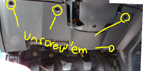
1. For better access, I removed the plastic panel underneath the passenger-side dashboard by removing 3 screws as indicated. The fourth lower-right screw is technically not holding the panel in place (it's holding a connector on the panel) but had to be loosened for the panel to come off (the screw is too long or something, in the way of the hinge underneath).
まず上部の3つのネジを外し、右下のネジを緩める。右下のネジはパネルの為ではないが外す際に引っかかるので、緩める必要あり。
2. The main relay is now visible to the left of fuse box, behind the open-hood lever. It's a gray box with a brown connector and is attached to the chassis of the car with a steel tab. Unbolt the (10-mm) bolt to detach the relay (and the tab) from the chassis.
メインリレーはヒューズボックスの左、ボンネットオープンレバーの奥。10mmのボルト。
3. After unbolted, the relay simply dangles. Disconnect the connectors by pulling jack and plug apart while pressing down the knob on the plug.
メインリレーのコネクタを外す。
3.Here's the close up of the relay assembly. I pressed a flat-head screwdriver against each of the latches to remove the cover.
取り出したメインリレーアセンブリ。マイナスドライバーを矢印のノブに押し当ててカバーを外す。
4. The exposed PCB. Several of the solder junctions are looking suspicious.
問題のプリント基板。いくつかはんだが甘くなっていそうな箇所発見。
READY TO WORK
5.After desoldering attempt. I sucked solder up just once per pad.
はんだ吸取器使用後。もう一度はんだづけするので、完全にはんだをとる必要は無し。
6. After resoldering. Perhaps not MIL-SPEC good but it looks better than the original. Skipping cleaning process as I do not have any PCB cleaner.
再はんだづけ後の基盤。まあ久しぶりにしてはまずまずの出来かな。少し汚いが良しとする。
7. Putting everything back. Reversing Step 3 down to Step 1.
カバーをかぶせ、ユニットを車に再装着、化粧パネルを戻す。
And the car STARTED! Of couse, this was not the for-sure sign of success as the symptom only manifests itself in a hot weather. It was pretty nice in the morning today. I'll have my fingers crossed and test it when it gets hotter.
で、エンジン無事かかった。でもかからなくなるのは夏の暑い日なので何ヶ月かは調子見。
我が老いたホンダのメインリレーを治してみました。
1. For better access, I removed the plastic panel underneath the passenger-side dashboard by removing 3 screws as indicated. The fourth lower-right screw is technically not holding the panel in place (it's holding a connector on the panel) but had to be loosened for the panel to come off (the screw is too long or something, in the way of the hinge underneath).
まず上部の3つのネジを外し、右下のネジを緩める。右下のネジはパネルの為ではないが外す際に引っかかるので、緩める必要あり。
2. The main relay is now visible to the left of fuse box, behind the open-hood lever. It's a gray box with a brown connector and is attached to the chassis of the car with a steel tab. Unbolt the (10-mm) bolt to detach the relay (and the tab) from the chassis.
メインリレーはヒューズボックスの左、ボンネットオープンレバーの奥。10mmのボルト。
3. After unbolted, the relay simply dangles. Disconnect the connectors by pulling jack and plug apart while pressing down the knob on the plug.
メインリレーのコネクタを外す。
3.Here's the close up of the relay assembly. I pressed a flat-head screwdriver against each of the latches to remove the cover.
取り出したメインリレーアセンブリ。マイナスドライバーを矢印のノブに押し当ててカバーを外す。
4. The exposed PCB. Several of the solder junctions are looking suspicious.
問題のプリント基板。いくつかはんだが甘くなっていそうな箇所発見。
READY TO WORK
5.After desoldering attempt. I sucked solder up just once per pad.
はんだ吸取器使用後。もう一度はんだづけするので、完全にはんだをとる必要は無し。
6. After resoldering. Perhaps not MIL-SPEC good but it looks better than the original. Skipping cleaning process as I do not have any PCB cleaner.
再はんだづけ後の基盤。まあ久しぶりにしてはまずまずの出来かな。少し汚いが良しとする。
7. Putting everything back. Reversing Step 3 down to Step 1.
カバーをかぶせ、ユニットを車に再装着、化粧パネルを戻す。
And the car STARTED! Of couse, this was not the for-sure sign of success as the symptom only manifests itself in a hot weather. It was pretty nice in the morning today. I'll have my fingers crossed and test it when it gets hotter.
で、エンジン無事かかった。でもかからなくなるのは夏の暑い日なので何ヶ月かは調子見。
Wednesday, March 9, 2011
Soldering Gear
Among several tools that I need for the project, I purchased soldering tools first:
I will be soldering for the front panel interface.
Actually, they will be used first to fix my car. My '93 Honda Civic (bought brand new in high school, thanks to my family moving back to Japan) is showing an age. Ever since we moved down to Louisiana in 2007 my car has been refusing to start (engine cranks but won't start) in hot weather under sun. And Louisiana gets pretty hot humid during June-Sept. It starts fine in the morning, but would not start in the afternoon... I've shown it to a couple mechanics, and neither had any idea of why. So, it happened again this past week (we get nice 80°F+ weather in early March) so I actually did a web search and found a website called Honda Acura E R. And whaddayaknow, its front page says "Main Relay Problem and Other Intermittent Starting Problems and Solutions." Ha, so it's not just me and my car, it's a common problem with Honda.
So, I studied the website a bit and concluded that I can fix it myself with a soldering iron and I need to get it anyway! So, I'll be working on this, too.
I will be soldering for the front panel interface.
Actually, they will be used first to fix my car. My '93 Honda Civic (bought brand new in high school, thanks to my family moving back to Japan) is showing an age. Ever since we moved down to Louisiana in 2007 my car has been refusing to start (engine cranks but won't start) in hot weather under sun. And Louisiana gets pretty hot humid during June-Sept. It starts fine in the morning, but would not start in the afternoon... I've shown it to a couple mechanics, and neither had any idea of why. So, it happened again this past week (we get nice 80°F+ weather in early March) so I actually did a web search and found a website called Honda Acura E R. And whaddayaknow, its front page says "Main Relay Problem and Other Intermittent Starting Problems and Solutions." Ha, so it's not just me and my car, it's a common problem with Honda.
So, I studied the website a bit and concluded that I can fix it myself with a soldering iron and I need to get it anyway! So, I'll be working on this, too.
Sunday, March 6, 2011
INTEC275 PC: Power Supply Options
Moving on to the power supply (PSU) considerations.
Again, the issue is the space space space. Assuming that I'll use a Mini-ITX motherboard (170 x 170 mm), PSU must be smaller than 100 x 79 x 308 mm... Most certainly a full-size ATX PSU is out.
There are basically 2 choices: Flex-ATX PSU or DC-to-DC converter with an external brick.
Flex-ATX PSUs (best known to be on Shuttle's XPCs) comes in the basic dimension of 150 x 81.5 x 40.3 mm (base model; there are longer models to accommodate higher output power). It cannot come in better dimension than this!
We don't need a lot of power, (Someone over at AVS Forum throwing 50 W as the power consumption for a Zacate-based HTPC.) But we want silence and 2 SATA power connections. And, I found a perfect unit:
FSP120-50GNF 120W Single FANLESS FLEX ATX Server Power Supply
newegg
Now, there are 2 concerns. First, there seems to be two versions of this PSU: one with 8 4-pin Molex connectors and another with 2 SATA power connectors. I want the latter, but it's not certain which one a store carries...
Secondly, it comes with 20-pin motherboard connector (not more modern 24-pin version) and has no 4-pin ATX 12V connector. Most motherboards released so far requires both (Asrock board seems to be the only exception). Now, there are adapters for both of these connections, but it would be the best if I don't need to invest in them.
For DC-to-DC converter route, the most prevalent option seems to be the PicoPSUs from Mini-Box.com.
For an ordinary setup, PicoPSU is a nice compact option, but the height clearance might be a problem for INTEC275 PC as it has a good chance to be located underneath the optical drive. Other options includes the Molex 80W unit.
I'm leaning towards Flex-ATX PSU route, but motherboard power requirement must be reviewed carefully.
Again, the issue is the space space space. Assuming that I'll use a Mini-ITX motherboard (170 x 170 mm), PSU must be smaller than 100 x 79 x 308 mm... Most certainly a full-size ATX PSU is out.
There are basically 2 choices: Flex-ATX PSU or DC-to-DC converter with an external brick.
Flex-ATX PSUs (best known to be on Shuttle's XPCs) comes in the basic dimension of 150 x 81.5 x 40.3 mm (base model; there are longer models to accommodate higher output power). It cannot come in better dimension than this!
We don't need a lot of power, (Someone over at AVS Forum throwing 50 W as the power consumption for a Zacate-based HTPC.) But we want silence and 2 SATA power connections. And, I found a perfect unit:
FSP120-50GNF 120W Single FANLESS FLEX ATX Server Power Supply
newegg
Now, there are 2 concerns. First, there seems to be two versions of this PSU: one with 8 4-pin Molex connectors and another with 2 SATA power connectors. I want the latter, but it's not certain which one a store carries...
Secondly, it comes with 20-pin motherboard connector (not more modern 24-pin version) and has no 4-pin ATX 12V connector. Most motherboards released so far requires both (Asrock board seems to be the only exception). Now, there are adapters for both of these connections, but it would be the best if I don't need to invest in them.
For DC-to-DC converter route, the most prevalent option seems to be the PicoPSUs from Mini-Box.com.
For an ordinary setup, PicoPSU is a nice compact option, but the height clearance might be a problem for INTEC275 PC as it has a good chance to be located underneath the optical drive. Other options includes the Molex 80W unit.
I'm leaning towards Flex-ATX PSU route, but motherboard power requirement must be reviewed carefully.
Wednesday, March 2, 2011
AvalonDock: Open-Source .NET Library
AvalonDock
I've been looking for a way to create a Windows app which has a bunch of dockable/floatable/tabbable panels, and this one might do it all for me.
Subscribe to:
Posts (Atom)