Saturday, May 21, 2011

Front Panel PCB Circuit Schematic


This PCB houses 8 buttons, 1 IR remote receiver, 1 LED, 1 VFD, and 1 30-pin FFC (flexible flat cable) connector along with several resistors and capacitors. Up on closer inspection (with the help of a multimeter) I was able to draw the schematic for this board:


Since I do not know the exact spec of the VFD (which has whopping 45 pins total but only 26 of them are actually connected), I've only indicated which VFD pins and FFC connector pins are connected.

The LED and IR receiver circuits are pretty straight forward.

The buttons, however, looked somewhat puzzling at first. But, further inspecting the main PCB (i.e., the other end of the FFC) revealed that both K0 and K1 are connected to an Onkyo proprietary front-panel control IC with pulled-up 2.7 kOhm resistors. In other words, there is a variable voltage divider which results in unique voltage at K0 or K1 for each button. The Onkyo chip has either a pair of A/D converter or of arrays of analog comparators.

What to do with Front Panel PCB

The initial idea was to design a replacement PCB with Noritake VFD and a socket for the Arduino Nano. However, I concluded that there would not be enough space for Arduino Nano and more importantly it is not very cost effective to order large sparsely filled board.

Instead, I've decided to design a smaller PCB to mount the Arduino Nano and connect it to the (modded) original front panel PCB.

  • Both IR receiver and LED circuits can be used as is.
  • Remove the original VFD, and attach the Noritake VFD PCB right on the vacated space. Interestingly, the height of the original VFD unit is pretty much the same as the height of the Noritake VFD module (VFD + PCB). The front panel PCB needs to be cut so that the 6-pin VFD connector is accessible.
  • Buttons. There are several alternatives here...

Button Circuit

I came up with 3 different approaches
  1. Use the existing voltage divider circuit with Arduino's ADCs
  2. Use 8-to-3 encoder (74148)
  3. Use Microchip 8-ch I/O Expander (MCP23S08)

Option 1. Use the existing voltage divider circuit with Arduino's ADCs


Pro:
  • Least amount of modification of the front panel PCB
Con:
  • More complicated Arduino firmware design
  • Arduino must monitor the buttons all the time and cannot be powered down.

Option 2. Use 8-to-3 encoder (74148)


Pro:
  • Interrupt-driven all-digital system
Cons:
  • Front-panel button circuits must be scrapped and rewired using jumper wires
  • Needs pull-up resistors

Option 3. Use Microchip 8-ch I/O Expander (MCP23S08)


Pros:
  • Clean interrupt-driven system
  • No extra hardware components (MCP23S08 has built-in pull-up circuits)
  • Each button press individually monitored
Con:
  • Front-panel button-related resistors must be removed and rewired using jumper wires

Verdict: Option 3 for simplicity, versatility, and "greenness".

Option 1 is appealing at first but ultimately got rejected due to its inability to power down the Arduino. Of the two digital, interrupt-driven approaches, Option 2 was the first one I considered (and tested) but went with Option 3 largely due to the pull-up resistor free design. Also, only Option 3 can detect of each button state change, which enables simultaneous multiple-button presses.

Saturday, May 14, 2011

INTEC275 PC: Main Internal Components

After much talk of AMD Zacate, I've decided to go with Intel Atom D525 for Intec275 PC. This rig is solely intended for music playback and CD ripping. Hence, the Zacate's advantage in graphics processing does not come into play. Plus, the Intel's D525 board costs $80 while the cheapest Zacate board is priced above $100.

So, in the end, here's what I got:


Component Manufacturer Model Cost
Motherboard+CPU Intel BOXD525MW $79.99
Memory Crucial (2 x 2GB) DDR3 1066 SO-DIMM $44.99
Power Supply FSP Group FSP120-50GNF 120W Single FANLESS FLEX ATX PSU $57.99
Hard Drive Western Digital WD15EARS Caviar Green 3.5" SATA 1.5TB $79.99
Optical Drive Panasonic UJ875A slot-loading slim DVD burner $16.00 (eBay)
Wireless NIC Intel Intel 622AN Mini PCI Express 6200 Centrino Advanced-N $20.95

A Couple Notes:

* Motherboard BIOS... The first thing when you buy an Intel motherboard is to flash its BIOS. Mine came with one that is 6 revisions older than the most current one (~10 mo old, it could just mean that it's not being sold well...) and Ubuntu had trouble with the default BIOS (locks up when CPU goes into deep sleep).

* 3.5" HDD... It's tight. I tried pre-fitting all the components into the Intec275 chassis and the HDD will be hanging over motherboard with 3/4" clearance. I may need to go to 2.5" HDD in the end. Fingers crossed.

* PSU version... I was hoping to receive the version 2 of FSP120-50GNF with SATA power and 4-pin 12V motherboard connectors but nope, got the first version with 4 strands of 4-pin molex connectors (8 connectors total). Bummer.

* Cables... In addition to above 2 power connector adapters, 2 coax cables for wireless antenna connection have to be purchased separately. Got a pair of 7" UL.FL to RP-SMA pigtail cables on their way now.

Thursday, May 5, 2011

XBMC -> MPD or XMMS2 based jukebox

I've started this project with intent of using XBMC as the base of my modded system. It appears to be a fantastic HTPC program. However, the INTEC275 PC is aimed to be a (digital) jukebox, i.e., not interested in supporting video playback feature. Also, the aim is to control it via the front panel VFD & buttons and via the remote control without monitor. So, XBMC's smooth UI will not be visible. All in all, XBMC is way over-spec'ed for the purpose.

So, I've been looking around for alternatives and came across 2 viable candidates:
Both are music player daemon (i.e., background service) and I will pick one of the two and develop the front-end interface program for INTEC275PC.

当初のプランはINTEC275PCをXBMCPCとして稼動するつもりだったのですが、XBMCは単純なジュークボックスにはぶっちゃけ向いていない(XBMCはビデオ再生が主目的)。なので、代わりを探してみたところ、丁度いい感じのミュージックプレーヤー・デーモンを2つほど見つけた: MPDXMMS2。(デーモンは悪魔ではなく、バックグラウンド動作するプログラム。)これからどちらか一つに絞って、INTEC275PC用のクライエントを自分で組む。

Sunday, April 24, 2011

Remote Control & Receiver Addendum

While implementing and testing the IR remote receiver program on Arduino (will be posted soon) I discovered another remote signal, which is vastly different from standard commands. When a remote key is held down for extended period, the remote repeatedly transmits the following signal (shown repeated twice):


Unlike the regular command signals, the start pulse is only 2.2 ms long (as opposed to 4.45 ms observed for regular commands), followed by (standard) signal low duration (0.6 ms).

Tuesday, April 19, 2011

Front Panel Controller: Arduino Nano


To interface the front panel buttons, IR receiver, and RI I/O with PC, I will use Arduino Nano. This board hosts an Atmel ATmega328 microcontroller (uC) and an FTDI FT232R USB-to-UART interface chip. Most of the ATmega328 GIO pins are made available (20 pins total), and the board can be powered solely by the USB bus power (although not sufficient for all of our needs).

The ATmega328 uC is equipped with 2 external interrupts (mapped to D2 and D3 pins) and 3 pin-change interrupts which can be software (semi-)selectable. The interrupts must be fully utilized to react to all user inputs (front-panel button presses, remote-control button presses, and RI input from the amp). It is also critical to wake Arduino from sleep state for it to power up the PC.

The idea is to mount this board on the (to-be-designed) front-panel PCB. Comparing its size to the original front-panel PCB indicates it can be doable.

Thursday, April 14, 2011

Remote Control & Receiver

This 60-key remote (RC-319S) is for the entire 2nd generation INTEC275 components (amp, 2 tape decks, tuner, MD player, and CD player). The INTEC275 CD player receives commands from this remote with a Sharp GP1U571X IR detecting unit (one on the PCB).


This detector is no longer produced (recall that the CD player is manufactured in the late '90). For the PC mod, I will use compatible detector from Sharp (GP1UM271RK0F, shown on the left above). This unit has the same band-pass filter center frequency (38 kHz) as GP1U51X and also has the exact same height profile as GP1U571X. The latter guarantees the GP1UM271RK0F to fit properly with the front panel plastic molding.

Experimenting with GP1U571X and the Onkyo remote

To test the IR detector, I hooked it up straight to 5V source and scope probe:


Here's the signal received when POWER button is pressed:

The detector outputs low (0 V) or high (4.5 V) levels. The output signal is normally high, and the beginning of received message begins with an extended period of low level (~9.11 ms), followed by a shorter period of high (~4.45 ms). The ensuing pulsing pattern defines the remote control command. But how is the information coded?

Upon closer inspection, we see that the low period duration is consistent all the time (~0.61 ms) while the high period duration is bi-modal (either 0.52 ms or 1.63 ms long). Hence, most likely it is pulse-length coded. There are 32 high periods during pulsating period; therefore, each button is coded with 32 bits (4 bytes).

For our convention, we let the short period to represent 0 Bit and the long period to represent 1 Bit. Also, the bits are transmitted in MSB first fashion. Accordingly, the 32-bit codes (in hex) associated with all 60 keys are listed below.

Row Col Code Button Name
1 1 0x4bb520df POWER
1 2 0x4bb59b64 SPEAKER A
1 3 0x4bb55ba4 SPEAKER B
1 4 0x4b36f807 INPUT SELECTOR PREV
1 5 0x4b367887 INPUT SELECTOR NEXT
2 1 0x4bb510ef SLEEP
2 2 0x4b3612ed TIMER
2 3 0x4b36c23d TIMER SETTING PREV
2 4 0x4b3642bd TIMER SETTING NEXT
2 5 0x4b36629d TIMER ENTER
3 1 0x4bb548b7 DECK-A REWIND
3 2 0x4bb58877 DECK-A FAST FORWARD
3 3 0x4bb5708f DECK-A REVERSE PLAY
3 4 0x4bb530cf DECK-A STOP
3 5 0x4bb5b04f DECK-A FORWARD PLAY
4 1 0x4bb558a7 DECK-B REWIND
4 2 0x4bb59867 DECK-B FAST FORWARD
4 3 0x4bb56897 DECK-B REVERSE PLAY
4 4 0x4bb5c837 DECK-B STOP
4 5 0x4bb5a857 DECK-B FORWARD PLAY
5 1 0x4bb518e7 DECK-B RECORD/PAUSE
5 2 0x4bb5906f TUNER FM
5 3 0x4bb550af TUNER AM
5 4 0x4bb5807f TUNER PRESET PREV
5 5 0x4bb500ff TUNER PRESET NEXT
6 1 0x4b7422dd MD REPEAT
6 2 0x4b7458a7 MD RECORD
6 3 0x4b7438c7 MD STOP
6 4 0x4b74f807 MD PAUSE
6 5 0x4b74d827 MD PLAY
7 1 0x4b74609f MD DISPLAY
7 2 0x4b74e01f MD SCROLL
7 3 0x4b7450af MD RANDOM
7 4 0x4b747887 MD PREV TRACK
7 5 0x4bb5d827 MD NEXT TRACK
8 1 0x4bb57986 CD DISC
8 2 0x4b361ae5 CD DISPLAY
8 3 0x4bb538c7 CD STOP
8 4 0x4bb5f807 CD PAUSE
8 5 0x4bb5b847 CD PLAY
9 1 0x4bb50af5 CD 1
9 2 0x4bb58a75 CD 2
9 3 0x4bb54ab5 CD 3
9 4 0x4bb57887 CD PREV TRACK
9 5 0x4bb5b847 CD NEXT TRACK
10 1 0x4bb5ca35 CD 4
10 2 0x4bb52ad5 CD 5
10 3 0x4bb5aa55 CD 6
10 4 0x4b36ea15 CD RANDOM
10 5 0x4bb5a05f MUTING
11 1 0x4bb56a95 CD 7
11 2 0x4bb5ea15 CD 8
11 3 0x4bb51ae5 CD 9
11 4 0x4b366a95 CD REPEAT
11 5 0x4bb540bf VOLUME UP
12 1 0x4bb55aa5 CD --/---
12 2 0x4bb59a65 CD 10/0
12 3 0x4bb5eb14 CD MEMORY
12 4 0x4bb51be4 CD CLEAR
12 5 0x4bb5c03f VOLUME DOWN

Note that the 8 MSBs (i.e., the first 2 hex digits) are always 0x4b, which can be used to identify the remote quickly. Otherwise, the codes appear fairly random. It would be interesting to know how they are chosen.

Wednesday, April 13, 2011

Noritake VFDs - Lesson: Read dimension specs correctly before ordering...


I thought GU280X16G-7003 would be *GREAT* for this project... The original VFD is 134 mm wide and 22 mm tall with display area of 113mm x 11 mm. I was reading the spec of GU280X16G-7003, which says 137.05 mm x 11.0 mm. "Perfect!" I was thinking (see this post).  Shortly after, I ordered it from Noritake online store and received the box a few days later.When I unpacked and had the VFD in my hand, I immediately had bad feeling. The dimension of the VFD is that of its display area, and the actual PCB dimension is whopping 182 mm x 33.5 mm...

After beating myself up over this for a few days, I ordered the half-size VFD (GU140X16G-7903) on sale. This module, which display area is half of GU280X16G-7003, can display full Japanese character set (Shift-JIS) which may be a good feature to have to display info of Japanese music or video.  (BTW, if you are interested in VFDs, noritake-vfd.com has great prices for their special sale promotion items.)

I've decided to keep GU280X16G kit as GU140X16G turned out to be just PCB module. The kit comes with a RS-232 cable with AC adapter prong, which is useful for development. The DB9 connector of the cable houses an IC chip to convert CMOS signals to RS-232. Because I prefer USB connection (neither of my desktop nor laptop PCs have serial port, does yours?) I actually disassembled the cable to keep the 2 cables.

VFD-PC Interface
Here's the pic of the actual device hookups:

FTDI's UB232R UART-to-USB interface module (the little PCB module on the breadboard) connects to the PC with mini-USB connection. Of 7 pins available on VFD's CN2 Connector, only 4 are use:

VFD CN2 Pin UB232R Pin Power Cable
Number Description Number Description Description
1 VCC (red) 5V (red)
2 SIN (brown) 8 TXD
3 GND (orange) 1 GND GND (orange)
4 SBUSY (yellow) 3 CTS#

Tuesday, April 12, 2011

CD Player In Pieces

Here we go.

All pieces removed from the chassis. No turning back now :)

The actual interior height is 67 mm. Also, the bottom plate is raised by 8 mm (to seat CD transport assembly on the plate). Even with 10 mm spacer to mount motherboard (which I/O rear panel is 44.45 mm tall) and FlexATX PSU (40.3 mm), the chassis is plenty tall enough for them.

Also, the depth of the chassis is deep enough so that the Mini-ITX motherboard (170 mm) and slim optical drive (126 mm), expecting less than 1 cm overlap. <sigh of relief/>

The front-panel PCB needs to be studied closely.
It hosts the VFD, IR Detector (remote control receiver), and 8 buttons. The dimension of the PCB will be measured precisely to produce the custom PCB for the PC front panel interface. The front panel buttons make contact with the tactile switches (5 mm tall, <<1 mm travel) on the PCB so when buttons are depressed the switches make contacts.


References:

ATX Specification v2.2 - formfactor.org
Form Factor of 5 1/4" 9.5mm and 12.7mm Height Optical Drives - SFF Committee

Sunday, April 10, 2011

PicoScope 2104: diyer's perfect solution

Here's my first impression on PicoScope, a USB Windows based oscilloscope by PicoTechnology (U.K.). I ordered the hand-held entry-level model (2104) from Newark.com. This scope is a compact (essentially a bulky probe with USB leads) and economical (~$200) solution, perfect for DIYers.


This is it. The body of the probe houses all the essential data-acquisition electronics, and any post-processing and the waveform display are performed on PC. The scope only requires a USB 2.0 connection as it is USB-bus powered.


The spec:

  • Vertical Resolution: 8bits
  • Analog Bandwidth: 10 MHz
  • Maximum Sampling Rate: 50 MS/s real-time
  • Time Base: 10 ns/div to 50 s/div
  • Buffer Size: 8k samples
  • Probe: 1M Ohm, 20 pF, AC/DC coupling
  • Voltage Ranges: ±100 mV to ±20 V in 1, 2, 5 V steps
  • Accuracy: 3% (voltage) and 100 ppm (time)
  • Connected and powered by USB
  • 5 year warranty
 Nothing earth shattering as expected from its price point.

Packaging: The scope came in a plain box,
which contains a scope storage bag and an intro-to-picoscope poster:
The scope is obviously in the bag along with Quick Start Guide, Software and Reference CD-ROM, and a bag of accessories.
The contents of the accessory bag:

The PicoScope Software installed smoothly on my PC and has been running hiccup free so far (Windows 7, Intel Core2Duo 3GHz, 4 GB memory). Here's a screen shot:
I find that the user interface is pretty straight forward and self-explanatory (that is, if you've used scopes in the past) based on my brief experience.

The body of the scope has 1 lighted button, which brings the start/stop control to the user's fingertip. Also, the button illuminates green (running) or red (not running) to indicate the scope's status:
As seen in the picture above, the probe tip is also lit, which helps tremendously to locate test points, IC legs, etc.


Wednesday, March 16, 2011

VFD & USB-to-UART Module

ここ(昔お世話になった方のブログ)でこんなものを発見。

My old over-the-internet Japanese acquaintance (whom I was grateful to hear his safety after the earthquake) posted a blog entry on using this USB-to-UART module (essentially an FTDI FT232R evaluation module):

In the U.S., we can get this little PCB piece from Mouser for $17.50 a piece. This looks a lot more appealing than other offerings such as this or this.

このモジュールの用途は前面パネルのVFD(蛍光表示管)を元の(Fig.A)からNoritakeの(Fig.B)に変える予定。このVFDモジュール(GU280X16G)CMOS 又は RS-232のインターフェースオプションがあるがCMOSの方を購入予定。(USBでPCに直接繋ぐか、インターフェースコントロール用のMCUを介して繋ぐかのオプションが出来るから。)

This module can be used to interface a Noritake VFD (Fig. B, which is to replace the original shown in Fig. A) with PC. There are 2 interface options for this VFD (GU280X16G): CMOS or RS-232. My plan is to go with the CMOS route so it can be connected to the PC directly (via USB module above) or indirectly via a microcontroller which checks the front-panel inputs (buttons & IR remote) even when the PC is off (more on this later).
Fig. A. Original VFD.

Fig. B. Noritake VFD.

Saturday, March 12, 2011

Car Fixin'

Armed with soldering tools, today I tackled the main-relay repair of my '93 Honda Civic according to Honda Acura E R.

我が老いたホンダのメインリレーを治してみました。

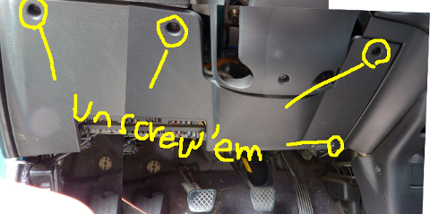
1. For better access, I removed the plastic panel underneath the passenger-side dashboard by removing 3 screws as indicated. The fourth lower-right screw is technically not holding the panel in place (it's holding a connector on the panel) but had to be loosened for the panel to come off (the screw is too long or something, in the way of the hinge underneath).


まず上部の3つのネジを外し、右下のネジを緩める。右下のネジはパネルの為ではないが外す際に引っかかるので、緩める必要あり。

2. The main relay is now visible to the left of fuse box, behind the open-hood lever. It's a gray box with a brown connector and is attached to the chassis of the car with a steel tab. Unbolt the (10-mm) bolt to detach the relay (and the tab) from the chassis.


メインリレーはヒューズボックスの左、ボンネットオープンレバーの奥。10mmのボルト。

3. After unbolted, the relay simply dangles. Disconnect the connectors by pulling jack and plug apart while pressing down the knob on the plug.


メインリレーのコネクタを外す。

3.Here's the close up of the relay assembly. I pressed a flat-head screwdriver against each of the latches to remove the cover.


取り出したメインリレーアセンブリ。マイナスドライバーを矢印のノブに押し当ててカバーを外す。

4. The exposed PCB. Several of the solder junctions are looking suspicious.


問題のプリント基板。いくつかはんだが甘くなっていそうな箇所発見。

READY TO WORK


5.After desoldering attempt. I sucked solder up just once per pad.


はんだ吸取器使用後。もう一度はんだづけするので、完全にはんだをとる必要は無し。
6. After resoldering. Perhaps not MIL-SPEC good but it looks better than the original. Skipping cleaning process as I do not have any PCB cleaner.


再はんだづけ後の基盤。まあ久しぶりにしてはまずまずの出来かな。少し汚いが良しとする。

7. Putting everything back. Reversing Step 3 down to Step 1.

カバーをかぶせ、ユニットを車に再装着、化粧パネルを戻す。

And the car STARTED! Of couse, this was not the for-sure sign of success as the symptom only manifests itself in a hot weather. It was pretty nice in the morning today. I'll have my fingers crossed and test it when it gets hotter.

で、エンジン無事かかった。でもかからなくなるのは夏の暑い日なので何ヶ月かは調子見。

Wednesday, March 9, 2011

Soldering Gear

Among several tools that I need for the project, I purchased soldering tools first:
I will be soldering for the front panel interface.

Actually, they will be used first to fix my car. My '93 Honda Civic (bought brand new in high school, thanks to my family moving back to Japan) is showing an age. Ever since we moved down to Louisiana in 2007 my car has been refusing to start (engine cranks but won't start) in hot weather under sun. And Louisiana gets pretty hot humid during June-Sept. It starts fine in the morning, but would not start in the afternoon... I've shown it to a couple mechanics, and neither had any idea of why. So, it happened again this past week (we get nice 80°F+ weather in early March) so I actually did a web search and found a website called Honda Acura E R. And whaddayaknow, its front page says "Main Relay Problem and Other Intermittent Starting Problems and Solutions." Ha, so it's not just me and my car, it's a common problem with Honda.

So, I studied the website a bit and concluded that I can fix it myself with a soldering iron and I need to get it anyway! So, I'll be working on this, too.

Sunday, March 6, 2011

INTEC275 PC: Power Supply Options

Moving on to the power supply (PSU) considerations.

Again, the issue is the space space space. Assuming that I'll use a Mini-ITX motherboard (170 x 170 mm), PSU must be smaller than 100 x 79 x 308 mm... Most certainly a full-size ATX PSU is out.

There are basically 2 choices: Flex-ATX PSU or DC-to-DC converter with an external brick.

Flex-ATX PSUs (best known to be on Shuttle's XPCs) comes in the basic dimension of 150 x 81.5 x 40.3 mm (base model; there are longer models to accommodate higher output power). It cannot come in better dimension than this!

We don't need a lot of power, (Someone over at AVS Forum throwing 50 W as the power consumption for a Zacate-based HTPC.) But we want silence and 2 SATA power connections. And, I found a perfect unit:

FSP120-50GNF 120W Single FANLESS FLEX ATX Server Power Supply
newegg


Now, there are 2 concerns. First, there seems to be two versions of this PSU: one with 8 4-pin Molex connectors and another with 2 SATA power connectors. I want the latter, but it's not certain which one a store carries...

Secondly, it comes with 20-pin motherboard connector (not more modern 24-pin version) and has no 4-pin ATX 12V connector. Most motherboards released so far requires both (Asrock board seems to be the only exception). Now, there are adapters for both of these connections, but it would be the best if I don't need to invest in them.

For DC-to-DC converter route, the most prevalent option seems to be the PicoPSUs from Mini-Box.com.


For an ordinary setup, PicoPSU is a nice compact option, but the height clearance might be a problem for INTEC275 PC as it has a good chance to be located underneath the optical drive. Other options includes the Molex 80W unit.

I'm leaning towards Flex-ATX PSU route, but motherboard power requirement must be reviewed carefully.


Wednesday, March 2, 2011

AvalonDock: Open-Source .NET Library

AvalonDock

I've been looking for a way to create a Windows app which has a bunch of dockable/floatable/tabbable panels, and this one might do it all for me.

Monday, February 28, 2011

AMD Fusion (Zacate+Hudson) ITX Motherboard List

The ideal CPU for the INTEC275 PC would be AMD's new Fusion (Zacate) APU. Here're the list of ITX motherboards that I found to date.

Make Model Price Form Factor
Asrock E350M1 $109.99@newegg.com Mini-ITX
Asrock E350M1/USB3 $119.90@newegg.com Mini-ITX
MSI E350IS-E45 $129.99@newegg.com Mini-ITX
MSI E350IA-E45 $139.99@newegg.com
$159.00@logicsupply.com
Mini-ITX
GIGABYTE GA-E350N-USB3 $149.99@newegg.com Mini-ITX
ASUS E35M1-I DELUXE $174.99@newegg.com* Mini-ITX
ECS HDC-I2 n/a Mini-ITX
ECS HDC-I2/E-240 n/a Mini-ITX
Jetway NC85-E350-LF$149.99@newegg.com Mini-ITX
Sapphire PURE Fusion Mini E350 $139.99@newegg.com Mini-ITX
Sapphire PURE White Fusion E350 $109.99@newegg.com Mini-ITX
FoxconnAHD1S n/a Mini-ITX

* Newegg took this mobo off its shelf as of 4/21/11 still listed on ASUS website though.

From my brief web search (see here) indicates that there are more to come. For example, Biostar and Zota have not released their Zacate/Hudson board. Yep, that's why I'm not in any hurry to make up my mind on motherboard :)

The concern of using one of these Mini-ITX boards is that the board (17cm x 17cm) extends enough so that the optical drive will cover up portion of the board. With < 79mm height of the case (even less between mobo and the drive), the motherboard heatsink may not fit under the drive. I will need to do more in depth assessment later.

In case that none of these motherboards are short enough, the alternative choices are
Make Model Price Form Factor
Intel D945GSEJT $99.95@logicsupply.com Mini-ITX
Via EPIA-N800 n/a Nano-ITX
Via EPIA-N700 n/a Nano-ITX
Via EPIA NX n/a Nano-ITX
Via EPIA NR n/a Nano-ITX

The Atom-based Intel board is a nice one. It's short (< 20 mm H). The combination of underpowered single-core Atom and GMA 950 graphics is a concern, but it may not be critical as I am not interested in 1080p video playback with this PC. Also, there are several people over on the AVS Forum already using this mobo for their HTPC with Marvell CrystalHD video decoder.

Via Nano-ITX boards have the ideal size (12mm  x 12mm) but they are not really geared towards multimedia (especially hi-def video playback). So, they will be the ultimate last resort when packaging completely falls apart.

The ideal scenario is for somebody to release Nano-ITX Fusion board... and I found this! It doesn't appear that they do business in the U.S., but I'm keeping my figures crossed someone in the U.S. will sell it (at a reasonable cost).

Update 4/21/11
Newly in-stock: Asrock USB3 version, Sapphire Pure White Fusion E350
Off the shelf: Asus E35M1-I DELUXE

INTEC275 PC 想定動作環境

オンキョーPC(INTEC275 PCとでも呼びましょうか)の動作条件。

やはり元がCDプレーヤーということで、そう格別高く想定しないし出来ない。やはり、シャーシの寸法が市販のMini-ITXのケース並の容積(特に高さ、ヒートシンクの選定に気をつけねば)しかないのが痛い。よって、PCのスペックは下記の条件を満たせれば良しとする。

  • メディアセンターのユーザインターフェースの感度が良好であること。
  • オーディオ再生(本当はサウンドカード付けたいが、スペースが絶対的に無いのでボツ)
  • DVD再生
  • マルチメディアサーバ機能
必要最小限のPCのコンポーネント(マザーボード、HDD、光学ディスクドライブ、DC-DCコンバータ)を如何にうまく配置出来るかが最初の肝になりそうだ。

でもって、一番の肝は元からのパネルの機能を完全に温存する事。C-722Mの前後のパネルの機能は下記の通り。

  • 前部パネル
    • CDのトレー
    • ボタン(8:Power・Eject・Play・Stop・Pause・Forward・Backward・Display)
    • Standby LED (スタンバイ時に点灯)
    • VFD (vacuum fluorescent display、蛍光表示管)
    • IR (赤外線)リモートのレシーバ
  • 後部パネル
    • オーディオ出力用RCA コネクタ(2、左右)
    • オンキョーRI 端子用3.5-mm モノラルミニジャック(2)
    • デジタルオーディオ端子 (光学/RCA、マザボによる)

Sunday, February 27, 2011

INTEC275 PC Specification

The primary goal of this project is to keep the user experience unchanged before and after as far as listening to CD. Hence, I'm not asking a lot as far as the PC spec is concerned. The PC should be able to provide:
  • Smooth Media Center UI experience
  • Stereo audio playback
  • Possibly DVD playback (shouldn't be a problem)
  • 7"/8" Touch screen control panel (only if I can find a unit that I like)
As far as the core PC components are concerned, the challenge is how to fit everything in the box. The external dimension of the chassis is only 275 mm (10.8") W x 79 mm (3.1") H x 308 mm (12.1') D, and the actual internal dimension would be even smaller.

The true challenge of this case mod is to keep all the original interfaces intact. C-722M has the following accessible to users:
  • On the front panel:
    • Optical disc drive access
    • 8 Buttons (Power, Eject, Play, Stop, Pause, Forward, Backward, Display)
    • Standby LED indicator (which is lit when the unit is not on)
    • VFD (vacuum fluorescent display)
    • IR remote receiver
  • On the rear panel:
    • 2 RCA jacks for left & right audio out
    • 2 3.5-mm mono jacks for Onkyo proprietary wired RI (Remote Interactive) cables
    • S/PDIF connection (optional, depends on motherboard support)

死に際の第2世代オンキョー INTEC275 CDプレーヤー

このプレーヤー、Onkyo C-722M、音飛びのみなので、まあ修理しようと思えば出来る(レーザーモジュールの交換が必要なだけ)けど、それじゃあ面白くないと。音源はどんどんオンラインに移ってるから、これからCDを買う機会もなくなるし(この過去5年でも5枚買ったかどうか)。もういっそのこと、中身をがっつり抜いてPC化してしまおう。という趣旨のプロジェクトのブログです。


米国在住のため 基本英語でのブログですが、(普段使わず鈍ってる)日本語の練習も兼ねて出来るだけ日本語のエントリも挙げて行く予定です。当然ながらコメント日本語OKです。

My Onkyo CD Player is on its last leg...

Well, not really. It still plays CDs OK. But it skips like crazy at the beginning of CDs (and don't you dare walk by it while it's playing, LOL). Yes, the problem can be fixed (by replacing the laser assembly, which costs anywhere from $50 to $100+), but that does not satisfy my craving of entering the world of PC case modding :)

Here's the unit, Onkyo INTEC275 C-722M (the "2G" model, product detail can be found here in Japanese):

The unit on the bottom is the matching INTEC275 integrated stereo amp unit (A-922M). Onkyo does not sell their INTEC product lines in the U.S. (or in the Europe based on a brief web search). As the name suggests (INTEC275) they are 275mm (10.8") wide. (Onkyo also makes INTEC205 series, which is even narrower at 205mm wide.)

This CD player was one of my prized possessions during my undergraduate years. Although I don't remember the exact time of purchase (circa 1997-98) I do remember hauling 2 heavy boxes (C-722M and a full-size Pioneer amp) with me back from Japan and paying import tax for them to the U.S. Customs at the airport. They were pretty darn heavy, and the tax was completely unexpected, but the system was well worth all these troubles in the end.

Anyway, the 15-year old CD player is dying (as expected to be) but I love its simple and elegant chassis design, and the matching amp is still going strong. At the same time, I don't listen to CDs as much as I use to, and my wife always tells me that she wants all CDs to be ripped and have them available on our home network. All these naturally leads to my long-time dream of PC case modding (all while she's rolling her eyes)!

So that's how this blog has begun, mainly to help me brainstorm the ideas and (hopefully) to show the actual modding progress.